“Little Britton” Ventilation Arrangement in Grosvenor Mine Designed to Maximize Potential Losing Control of Goaf and Initiating Spontaneous Combustion. Greatest area of risk MG 103 C heading 39 to 41 cut-through
“Little Britton” Longwall Ventilation Arrangement or “Little Britton” for short and easy future reference.
Whatever the Inquiry findings are, whenever they are handed down.
There are few of the design criteria for control of the goaf, and minimizing the risk of a spontaneous combustion event, Grosvenor Senior Officials have not completely ignored.
 .
.
I can find nothing remotely like it except for something called Double Entry Retreating with back bleeder (return) used in the USA.
As no one else has been able to come up with a name for this bastard child of someone’s imagination
I shall christen thee “Little Britton” Longwall Ventilation Arrangement
If I was looking for the most likely location of potential spontaneous combustion, evaluating “Little Britton” from Ventilation Design and Spontaneous Combustion First Principles.
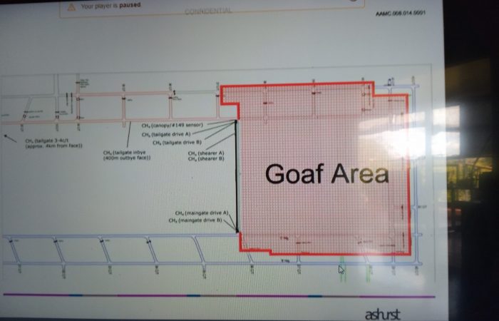
I would look no further than in the area of MG103/TG104 C hdg 39 to 41ct marked in attached diagram

We know now that the Grosvenor has to employ 2 fans in a forcing arrangement to provide roughly 50m3/s at around a positive pressure of 600Pa.
This is through a downcast shaft delivering refrigerated air from behind the Tailgate, then past 20PSi (140kPa) goaf seals along the back of the goaf.
Then past the other newly installed 20Psi seals down 104 Maingate and then mixes with air coming from the mains and then goes into the longwall face.
Oxygen is being pushed into the goaf at each and every one of these seals
The greatest pressure differential possible for the mine to dream up and create has been achieved.
What is the pressure differential across the Seals at the back of the longwall face?
In particular C Hdg 40 to 41 c/t MG 103?
Was it even measured?
Or is it just taken off a flawed Ventsim Model not validated by a full pressure quantity survey of the Mine?
Why you need to have it in a forcing arrangement to get it to work pumping refrigerated air down the shaft is a question only the Ventilation Officer and others can answer.
There exists at the point of greatest pressure differential MG103/TG104 C hdg 39 to 41ct
Small and dewatered coal pillar subject to some abutment pressure.
Any potential products of oxidation from this area report to C heading sewer road that is not monitored until main LW return at 3 to 4 c/t B heading (wherever TB #39 is actually located and sampling).
If there was something occurring in this area, GR04V003 to 4 might pick it up.